Case note · a boiler house in Pakistan · October 2026

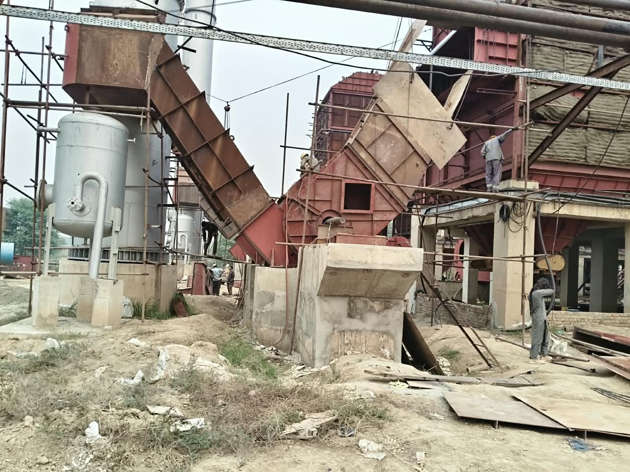
Photo: the customer’s boiler house. The new drive goes on the same 690 V bus as an existing 1250 kW unit.
A boiler house in Pakistan needed a 400 kW induced draft fan to run at variable speed on a 690 V bus. The customer’s own requirement asked for a drive with input and output reactors built in.
We quoted a drive without them, and put the reactors outside the cabinet. That part was settled in one exchange. The reactor percentage took longer.
The order that came out of it: CD110-400G-6, 400 kW, 690 V, 430 A, IP20. Input reactor 2%, output reactor 1%, both external, 690 V, 550 A, copper winding. We had recommended 4% on the input side. The difference is in writing.
The requirement, as the customer wrote it
Four lines, no model number:
- 400 kW
- 670–720 VAC, three phase
- input and output reactor built into the drive
- boiler induced draft fan duty
670–720 VAC is a band around a 690 V nominal system. We read the duty as 690 V and sized the drive at 430 A on that basis.
An induced draft fan is not a pump. It runs against the furnace draft, it runs continuously, and it does not like being stopped quickly. That last point came back later in the file.
The cabinet has no reactor inside, so the reactors went outside
The CD110-400G-6 has no reactors inside the cabinet. Not a stripped version, not a cost shortcut. It is how the model is built.
Two ways to answer a specification like that: argue the requirement away, or supply the reactors separately. We did the second. The customer agreed, and the order changed shape: one cabinet plus two external reactor units.
The CD110 cabinet: 400 kW, 690 V, 430 A, IP20, 55 kg, packing 845 × 1395 mm.
Two reactors, outside the drive
Both units are 690 V, 550 A, copper winding, class H insulation, AN cooling, IP00, 50 kg each, packing 450 × 350 × 300 mm.
Same frame, two different jobs. The input reactor sits between the transformer and the drive. The output reactor sits between the drive and the fan motor, at the far end of a long cable.
690 V reactor, copper winding, 550 A. One unit on the input, one on the output.
What the site data added
The customer sent one handwritten page. Four numbers on it changed the discussion.
- 6% — transformer short-circuit impedance
- 98 m — cable from the drive to the fan, outdoors
- 326 A — motor current, continuous running
- 1250 kW — another drive on the same bus
Plus the conditions around them: 24 h running, altitude under 1000 m, ambient 15–55 °C, motor class F insulation.
The customer’s handwritten site data: 690 V transformer, 6% short circuit, 98 m cable, 326 A continuous.
Read together, these are not four separate facts. A 6% transformer is a relatively soft source. 98 m outdoors means the cable is long and the motor sits away from the cabinet. And a 1250 kW drive already shares that bus, so a large switching load is present before our drive is even connected.
Why we asked for 4%, and why the order says 2%
At 430 A and 690 V, reactor percentage converts to inductance like this: 4% is about 0.118 mH, 2% about 0.059 mH, 1% about 0.0295 mH. The percentage is not a label. It is a physical size.
We recommended 4% on the input. The reason we gave the customer: a 6% transformer, 98 m of cable and a 1250 kW neighbour on the bus leave the drive with less headroom against voltage dips and current distortion, and published reactor guidance treats 4% as the harmonic-filtering range while 1.5–2% is mainly transient suppression.
The customer stayed at 2%. That still does a real job: it adds impedance ahead of the rectifier and helps with nuisance tripping. It filters less than 4%. We put the recommendation and the decision in writing, side by side, so the file shows what we asked for and what was ordered.
The output side stayed at 1%. Drive manuals commonly list a 1% output reactor for 30–100 m of shielded motor cable. At 98 m this site sits inside that band, at the top of it.
The stop question: coast, not ramp
This fan does not stop when the drive stops. The flue keeps pulling air through the boiler, the impeller keeps turning, and the motor becomes a generator.
A ramp stop tries to hold the fan on a deceleration curve. The energy from the windmilling impeller has nowhere to go, so the DC bus climbs until the drive trips on overvoltage.
A coast stop switches the output off and lets the fan spin down on its own. That is the mode this site runs, and it is the mode written into the order. If a plant needs a controlled stop instead, the drive needs a braking unit and a resistor — a different order, and better decided before the cabinet is built than after.
Configuration at a glance
| Item | Value on this order |
|---|---|
| Drive | CD110-400G-6, 400 kW, 690 V, 430 A, IP20,126kg |
| Input reactor | External, 690 V, 550 A, 2%, about 0.059 mH, copper, IP00, 50 kg |
| Output reactor | External, 690 V, 550 A, 1%, about 0.0295 mH, copper, IP00, 50 kg |
| Motor | 326 A continuous, class F insulation |
| Cable | 98 m, outdoors |
| Transformer | 6% short-circuit impedance |
| Same bus | 1250 kW drive |
| Stop mode | Coast stop |
| Site conditions | 24 h running, below 1000 m altitude, 15–55 °C ambient |
If you are sizing a 690 V drive for a fan
- Check whether the reactors are inside the cabinet before you compare prices. A drive without them needs two external units, panel space and wiring.
- Size the reactor percentage from the transformer impedance, the cable length and what else sits on the bus. A catalogue default says nothing about a 6% source with a 1250 kW neighbour.
- At 98 m outdoors, keep the output reactor close to the drive and match the cable type to what the drive manual’s cable-length table assumes.
- Ask about stop mode in the first meeting. For an ID fan on a furnace draft, coast stop is usually the answer; a ramp stop can be an overvoltage trip waiting to happen.
Questions this case usually raises
Does a 690 V drive need an input reactor if it has none inside? Not always. On a soft source, with a long cable and large drives on the same bus, it is the normal move. Here we asked for 4% and the order went to 2%.
What is the difference between 2% and 4% on the input? Impedance and physical size: about 0.059 mH against 0.118 mH at 430 A, 690 V. More impedance means more filtering and more headroom, at a higher price and a slightly higher voltage drop.
Can a VFD ramp-stop a boiler ID fan? Usually not without braking. The furnace draft keeps the impeller turning, the motor regenerates, and the DC bus rises. Coast stop avoids that.
How long can the motor cable be? It depends on the drive’s own cable-length table and the cable type. A 1% output reactor commonly covers 30–100 m of shielded cable.