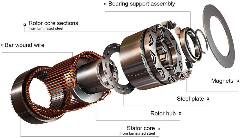
I. Permanent Magnet Synchronous Motors
1. Principle of Permanent Magnet Synchronous Motors In a super – high – efficiency permanent magnet synchronous motor, the rotor is excited by rare – earth permanent magnets, eliminating the necessity for excitation current. During the motor’s operation, this absence of excitation current results in no resistance loss within the rotor and a reduction in resistance loss within the stator. Consequently, the overall loss of the motor is decreased by 20%. Moreover, as the magnetic field of the permanent magnet motor is generated by rare – earth permanent magnets, there is no need to augment the reactive excitation current in the stator. This enables a significant enhancement in the power factor of the motor, reaching a range of 0.95 – 1. Subsequently, the current within the stator winding of the motor is substantially reduced, thereby elevating the motor’s efficiency by 2 to 6 percentage points. This performance meets and surpasses the international IE3 – IE4 standards, endowing the motor with characteristics such as high efficiency, a high power factor, low running current, low temperature rise, a wide economic operating range, and substantial power – saving returns.
2. Advantages of Permanent Magnet Synchronous Motors When compared with ordinary motors, permanent magnet synchronous motors possess several distinct advantages:
1) Constant Rotational Speed: The rotational speed remains constant and is equivalent to the synchronous rotational speed.
2) High Power Factor: During normal operation of a permanent magnet motor, the rotational speed of the rotor synchronizes with that of the stator magnetic field. This synchronization leads to the absence of current in the rotor squirrel – cage bars and a subsequent reduction in the induced current within the stator. Hence, a high power factor is achieved.
3) High Operating Efficiency: In the normal operation of a permanent magnet motor, the presence of permanent magnets on the rotor suffices to ensure the motor’s normal functioning. As a result, there is no current in the rotor squirrel – cage bars, eliminating winding losses. Additionally, there is no rotor iron loss. Consequently, the efficiency of the permanent magnet motor is significantly higher than that of ordinary motors.
4) Wide Economic Operating Range: The economic operating range of ordinary motors typically spans from 60% to 100% of the rated load. When the load falls below 60% of the rated load, the efficiency and power factor curves of the ordinary motor decline rapidly, leading to low operating efficiency and power factor. In contrast, the economic operating range of permanent magnet motors is far broader. Not only does it exhibit high efficiency at the rated load, but it also maintains a relatively high efficiency within the range of 25% – 120% of the rated load. The efficiency curve is relatively smooth with minimal variation. The motor efficiency generally remains no lower than 80% of the rated efficiency. In contrast, for ordinary motors, the efficiency plummets near 35% of the rated load, reaching as low as 30% – 40%. For permanent magnet motors, even at a 25% load, the power factor can exceed 0.9, with the power factor increasing as the load lightens. For ordinary motors, the power factor drops rapidly from approximately 0.85 at the rated load to below 0.5.
5) Compact Size and Light Weight: Owing to the utilization of rare – earth permanent materials in the rotor of the permanent magnet motor, which results in low losses, high efficiency, and a high power factor, for the same power output, the permanent magnet motor can be designed with a smaller volume and lighter weight compared to ordinary motors while maintaining efficiency and power factor.
6) High Locked – Rotor Torque Multiple: The locked – rotor torque multiple of ordinary motors generally ranges from 1.6 to 2.3 times the rated torque. In contrast, the locked – rotor torque of permanent magnet motors can typically reach 2.4 times or more of the rated torque.
7) High – Efficiency Low – Speed Operation: Ordinary motors with more than 10 poles are relatively rare because the efficiency tends to decrease as the rotational speed decreases. However, permanent magnet motors can achieve advanced technical specifications, with designs featuring 24 poles or even 32 poles. This allows for very low rotational speeds, enabling direct – drive applications for certain equipment and eliminating the need for reduction gears. From an energy – conservation perspective, this configuration enhances overall efficiency.
II. CD200S Series Synchronous Frequency Drive
1. Product Features The CD200S series frequency converters are high – performance vector – type frequency converters, characterized by rich and robust functionality and excellent and stable performance. These converters are capable of driving both three – phase AC asynchronous motors and three – phase AC permanent magnet synchronous motors. In terms of controlling and adjusting motor torque and speed, as well as providing high – torque output at low speeds, they exhibit outstanding dynamic performance and possess an extraordinary overload capacity. The CD200S series supports various types of IO expansion board cards, PG board cards, and communication expansion board cards, making them widely applicable in diverse automated production equipment and production lines.
1) Incorporating a digital signal processor (DSP) dedicated to motor control, supplied by American TI Company, with a main frequency of up to 150 MHZ.
2) Utilizing the fourth – generation IGBT module from Infineon, in conjunction with its maximum junction temperature characteristic of 175°C, and implementing a novel PWM modulation approach. This combination further reduces switching losses, enabling the drive to operate without derating even under an environmental temperature of 50°C.
3) Supporting the driving of both asynchronous and permanent magnet synchronous motors.
4) In the V/F control mode, high – precision current – limiting control is implemented. This ensures that the drive remains free from over – current alarms during rapid acceleration and deceleration or locked – rotor conditions, thereby providing reliable protection for the drive. In the vector control mode, high – precision torque – limiting control is employed. This allows the drive to output either strong or gentle torque in accordance with the user’s process control requirements, thus ensuring reliable protection for mechanical equipment.
5) Process PID control with a plethora of given and feedback methods.
6) Supporting DC power input, thereby facilitating users in formulating application schemes for common DC busbars.
7) Over – voltage stall protection mechanism.
8) Under – voltage regulation functionality.
9) Over – current stall protection function.
2. Product Operating Environment
Product Installation Location: Indoor
Environmental Temperature: Maximum Temperature: +40°C; Minimum Temperature: -10°C
Altitude: Less than 1000m.
Average Daily Relative Humidity: Not exceeding 95%;
Average Monthly Relative Humidity: Not exceeding 90%.
Earthquake Intensity: Not exceeding 8 degrees.
Indoor Environmental Pollution Level: II Level
Similar Posts
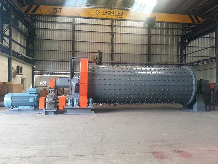
Ball Mill Frequency Conversion Retrofit Program
Power Consumption Analysis at Working FrequencyA ball mill needs to run for 19 hours. First, start…
Solution for Music Fountain Operation
Introduction: The original fountain control system uses the main phonemes of music (frequency, amplitude, timbre, and…
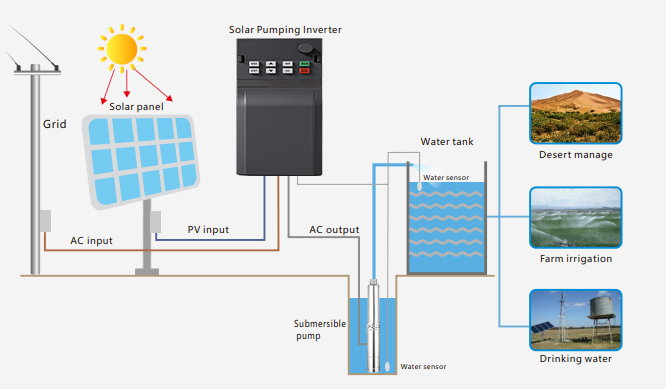
Application of Solar Pump Inverter
Introduction: In the contemporary era, with the energy crisis intensifying globally, Invtar’s vigorously promotes the concept…
Solutions for Multi-pump Constant Pressure Water Supply
1. Introduction: The control of the water supply system ultimately aims to meet users’ demand for…
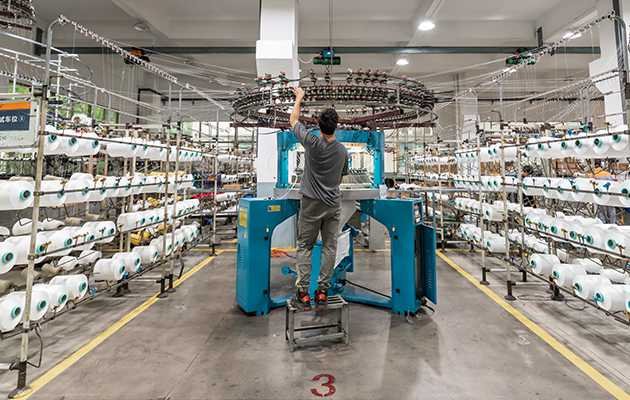
Dedicated VFD for Alternative Torque Motor Winding Solution
Process Requirements 1. The torque motor exhibits the following characteristics: It has relatively soft mechanical properties….