I. Safety Precautions
1. Installation must be performed by professional electrical personnel with electrical expertise, familiarity with the operation site, equipment status, and electrical skills.
2. Confirm the voltage class of the equipment (e.g., low – voltage AC380V) and verify if it’s live.
3. When working with electricity, wear insulating shoes and gloves or stand on a dry board. Tools must be fully insulated and avoid contact with different – phase power sources and metal frames during live work.
4. For power – outage operations, handle work tickets, conduct power outages, check for electricity, install ground wires, and set up safety fences or hang warning belts.
5. Low – voltage device or line operations require at least two people, with a dedicated supervisor.
II. Installation Precautions
1. Installation Environment
-1.1 Ambient Temperature: Inverters, like other electronic equipment, require an ambient temperature typically in the range of – 10 to + 40℃. As high – power devices, they’re sensitive to temperature. For safety and reliability, it’s best to keep the temperature below 40℃. The rated output current decreases by 1% for each 1℃ increase. High and fluctuating temperatures can reduce the inverter’s insulation and lifespan.
-1.2 Environmental Humidity: Inverters need relative humidity of the surrounding air to be ≤ 95% (no condensation). Add desiccant and heaters to the inverter cabinet as per the site environment.
-1.3 Vibration and Impact: Inverters should be protected from vibration and impact. Mechanical vibrations can cause loosening of connections, leading to electrical faults. Besides strengthening the control cabinet and avoiding vibration sources, use anti – seismic rubber gaskets outside the cabinet and cushioning rubber pads between devices and the installation plate. Regular inspection and maintenance are necessary.
-1.4 Electrical Environment:
-1.41 Prevent Electromagnetic Interference: Inverter components and software can malfunction due to electromagnetic interference. To avoid this, keep input power, output motor, and control lines separated. Keep sensitive equipment and signal lines away from the inverter. Use shielding cables for key signal wires and ground the shielding layer using the 360° grounding method.
-1.42 Prevent Input Terminal Overvoltage: The main circuit of the inverter is sensitive to overvoltage, which can cause permanent damage. In cases of power supply fluctuations (e.g., from factory – owned generators), take preventive measures.
-1.5 Altitude: Inverters can output rated power at altitudes below 1000m. Above this, the output power decreases. At 4000m, the output current is 40% of that at 1000m.
-1.6 Other Environments: Avoid installing inverters in places with rain, dew, dust, cotton, metal dust, grease, salt, radioactive materials, or combustibles.
2. Installation Method and Heat Dissipation Treatment
Inverters generate heat during operation, with power losses of about 40 – 50W per 1kVA of capacity. Consider heat dissipation during installation.
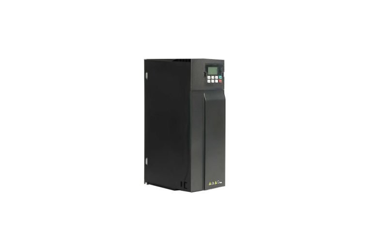
-2.1 Wall – mounted Installation:
Inverter housings are usually sturdy for wall – mounting. Install vertically for good ventilation. Keep a distance of at least 100mm on both sides and 150mm above and below the inverter. Install a baffle above the air outlet to prevent debris blockage.
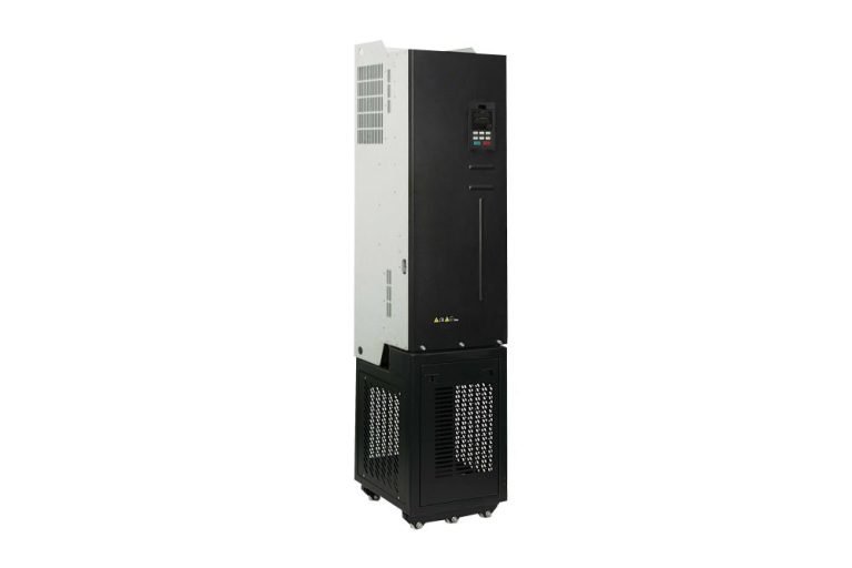
-2.2 Cabinet Installation:
Use cabinet installation in dusty, humid environments or when there are many peripheral accessories. Precautions: For a single inverter with internal cabinet cooling, install a ventilation – type cooling fan directly above it. For multiple inverters, install them side by side if possible; if longitudinal installation is necessary, use a baffle between them.
3. Inverter Wiring
-3.1 Main Loop Wiring:
-3.11 Inverter Three – phase AC Input Terminal (R, S, T)**: Connect the power input terminal to the three – phase AC power supply through a circuit breaker for line protection. Do not connect the three – phase AC power supply directly to the output terminal.
-3.12 Inverter Three – phase AC Output Terminal (U, V, W)**: Connect the output terminal to the motor in the correct phase sequence. Reverse the motor direction by exchanging any two phases or through parameter settings. Do not connect to phase capacitors or surge absorbers.
-3.13 DC Reactor Connection Terminal (DC +.p +)**: Connect the DC reactor terminals for power factor improvement. When using the DC reactor, remove the short – circuit conductor.
-3.14 Connection Terminal of Brake Unit (DC +.BK)**: Small – power inverters (0.75 – 11kW) have a built – in brake unit (brake resistance is extra), while those above 15kW need external brake units and brake resistances.
-3.15 DC Power Input Terminal (DC +, DC -)**: The DC input terminals of the external brake unit are the positive and negative of the DC bus.
-3.16 Grounding Terminal (PE)**: Inverters produce leakage current, which increases with carrier frequency. Ground the inverter and motor for safety.
-3.2 Matters Needing Attention:
-3.21 Grounding resistance should be less than 10Ω. Determine the wire diameter of the grounding cable based on the inverter’s power.
-3.22 Do not share the ground wire with welding machines or other power equipment.
-3.23 If the power supply line has a common zero – ground, consider laying a separate ground wire.
-3.24 If multiple inverters are grounded, connect them separately to the earth to avoid forming a circuit.
-3.3 Control Loop Terminals Wiring:
-3.31 Use stranded shielded wire for the control loop connection to avoid interference – caused misoperation.
-3.32 Lay the control line separately from the main loop cable, at a distance of more than 100mm. Avoid parallel or cross – laying with the main circuit; if crossing is necessary, do it vertically.
-3.33 Use a grounded metal pipe or shielded cable for cable shielding. Connect one end of the shielding layer to the common end (COM) of the inverter control circuit (not the ground end Pe), and leave the other end suspended.
-3.34 For switch – quantity control lines, twist the two lines of the same signal together with a small spacing. Connect the shield layer to the earthing end of the inverter. The signal line and cable should not exceed 50m.
-3.35 Ground the weak – voltage current loop wire at one point on the inverter side using a dedicated grounding terminal.
4. Inverter Lightning Protection
Lightning protection is crucial for inverter safety, especially in lightning – active regions or seasons. Current inverters usually have a lightning absorption network, but for overhead power lines, additional measures are needed. Options include installing a special inverter lightning arrester at the power supply inlet line, using an embedded steel tube 20m away from the inverter for earthing protection, or implementing a lightning protection system in the control room for cable – introduced power.

Similar Posts
Safety Precautions for Low voltage Soft Start
Before installing or operating the low – voltage soft starter, thoroughly read and understand the low…
Installation Precautions for High voltage Frequency Inverter
1.1 Safety Precautions Before electrical wiring, equipment operation, inspection, and maintenance, thoroughly read this manual to…