Introduction: The original fountain control system uses the main phonemes of music (frequency, amplitude, timbre, and tempo) to control the combination of water spray pattern changes, water column height, distance variations, and light color combinations. The principle is to convert sound signals into electrical signals. After amplification and other processes, these signals drive relays or electronic switches to control the opening and closing of solenoid valves on waterways, thereby controlling the on – off of nozzle water circuits. The musical fountain combines modern technology and art, and using fountains to express the beauty of music is visually appealing. Currently, many music fountains with various control systems have achieved good results. However, among these sound – controlled products, some use the time – domain changes of music to control the fountain, and some divide the music…
1. Advantages of PLC & Inverter Control Scheme
In many music fountain control systems, whether using relay control or solenoid valves to control the musical fountain (switch and fountain head control), these methods respond slowly as they can’t regulate motors or other control valves. So, this design focuses on the synchronous real – time nature of music and fountains. In the control system, variable – frequency speed control is used, with the inverter controlling the motor for rapid response.
1.1 Song Play
The music for the musical fountain can be played from CD, VCD, DVD players. Through the power amplifier, the selected song is divided into two channels. One channel is output to the speaker, and the other to the audio converter module for audio signal sampling. After the operator selects a demo tune from the music database, the driver is started and the tune is played correctly.
1.2 Water Type and Music Synchronization Control
When the music starts playing, the water type synchronizes. Between the end of one music piece and the start of the next, the water model stops simultaneously and resumes later. This music fountain control system allows for adjustable fountain delays to synchronize water types and music.
1.3 Water Type Rhythm Follow – up Control
For different music, the jumps and swings of the water type synchronize with the music rhythm, showing the passion and vitality of the musical fountain. These jumps and swings are represented by corresponding programs after the audio converter acquires and converts the audio signal. The frequency converter controls the acceleration and deceleration of the submersible pump to present different views for different music signals.
2. Music Fountain Hardware Components
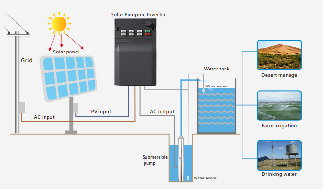
The hardware system mainly consists of a PLC , an audio conversion module, a frequency converter, and a submersible pump. The PLC samples and converts external audio signals to control the frequency converter’s operation, achieving the control system’s requirements and real – time perfect combination of music and fountain. The hardware components of the music fountain control system are shown in Figure 2.1.

3. Control Principle
The main circuit diagram of the control system mainly includes the inverter and submersible pumps. The power line of the frequency converter is directly connected to the three – phase AC power, with connections to terminals R, S, and T respectively. The output is to the submersible pump, which is connected to terminals U, V, and W. The control system’s inverter in the circuit has rich protection functions, effectively protecting the system’s stable operation. The frequency changer DI1 is controlled by the PLC’s DO output for start – stop, and AI1 is given the PLC’s analog frequency. Different analog signal outputs change the speed of the submersible pump. The specific circuit diagram of the control system is shown in Figure 3.1.

The inverter’s speed regulation is only determined by the external PLC signal, and various speeds can be output through analog quantity. Even during operation, speeds (frequencies) from 0 to 60 Hz can be arbitrarily set.
4. PLC Software Control Section
4.1 Main Program Flow Chart
As shown in Figure 4.1, when the PLC runs, it starts parameter initialization and scans the system program. When the start button is pressed, the system main program does the following: start timing, read the value in AIW0 every s. The stored value goes to the accumulator AC0. AC0 is compared with the internal set value to determine which subroutine to call. After selection, the subroutine runs and the routine ends.

4.2 Stopped Flow Chart
When the system needs to be shut down, press the stop button directly regardless of the situation, and the PLC will stop all work. [Figure 4.2 shown]